
Industry-news
LED display application notes
Through Hole Display Mounting Method
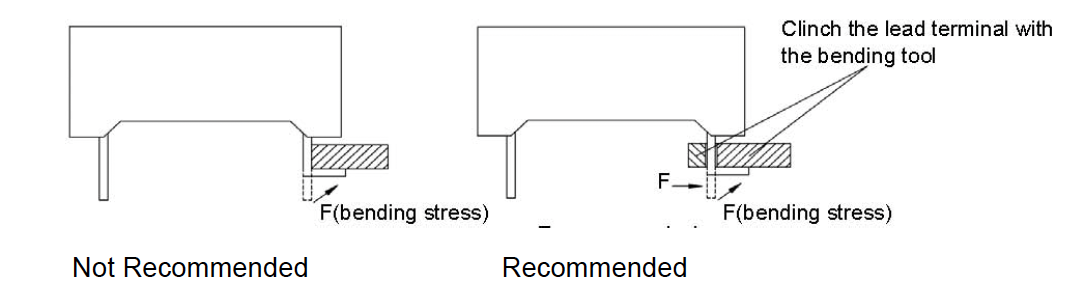
Lead Forming
Do not bend the component leads by hand without proper tools. The leads should be bent by clinching the upper part of the lead firmly such that the bending force is not exerted on the plastic body.
Installation
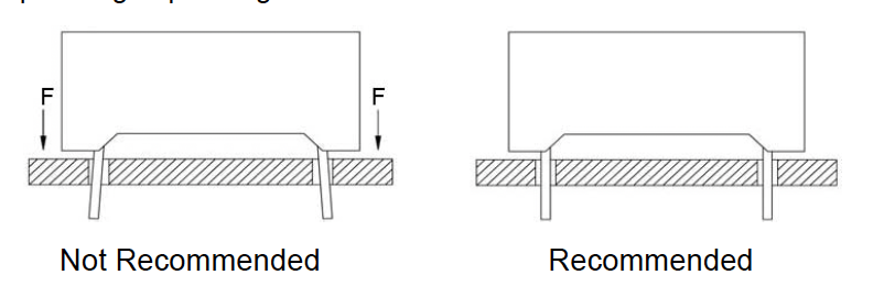
1.The installation process should not apply stress to the lead terminals.
2.When inserting for assembly, ensure the terminal pitch matches the substrate board’s hole pitch to prevent spreading or pinching the lead terminals.
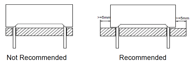
3.The component shall be placed at least 5mm from edge of PCB to avoid damage caused excessive heat during wave soldering
4 .When performing automated mounting, board bending, and lead-trimming or clinching operations, the stress may damage the resin body. In particular, caution should be taken when clinching or cutting the leads, since the amount of force applied during this time is significant. Therefore, test samples should be run through the lead-forming process then pass through soldering to be check for possible damage before mass production begins.
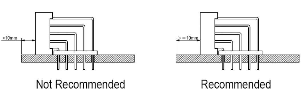
5. For products with 90-degree lead bends, ArkTech recommends at least 10mm of clearance between the display and the edge of the PCB during soldering and assembly.
Display Soldering Conditions
The recommended conditions for soldering are as follows. Because the component is made with epoxy resin, the units are susceptible to heat. Therefore, the preheating and soldering temperatures should be kept as low as possible to avoid damage.
1 . Manual Soldering Conditions (with 1.5mm Iron tip ) Iron Tip
Temperature: 350°C Max, Time: 3s Max
Position: The iron should be situated at least 2mm away from the root of the leads.
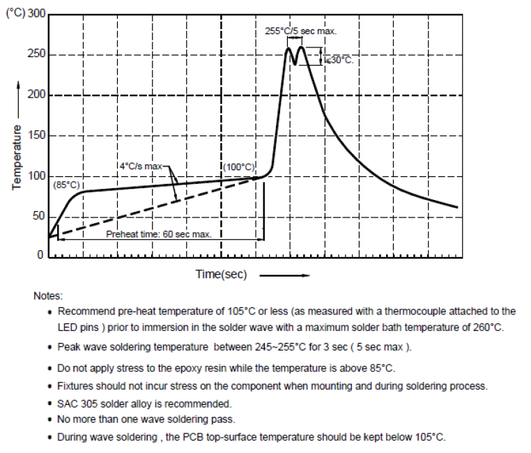
2 . Through the Wave Soldering Conditions
Wave Soldering Profile For Lead-free Through-hole LED
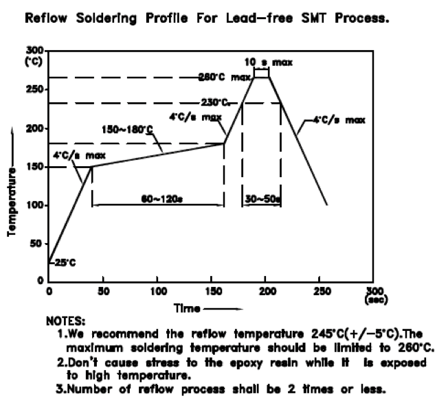
3. Reflow Soldering Profile for SMD Display
4.Soldering General Notes:
1. ArkTech recommend manual soldering to be used only for repair and rework purposes. The soldering iron should not exceed 30W in power. The tip of the soldering iron should not touch the reflector case to avoid heat-damage.
2. Maintain the pre-heat and peak temperatures with dip units as low as possible and the times as short as is feasible, since the products are susceptible to heat during flow soldering.
3. After soldering, allow at least three minutes for the component to cool to room temperature before further operations.
4. Through-hole displays are incompatible with reflow soldering.
5. If components will undergo multiple soldering processes, or other processes where the components may be subjected to intense heat, please check with ArkTech for compatibility.
6. According to IPC-A-610D standards, the wetted fillet (Class 1) or minimum fillet height for25%castellation height is acceptable for the soldering specification of our SMD display.
Cleaning
1. Mild “no-clean” fluxes are recommended for use in soldering.
2. If cleaning is required, ArkTech recommends to wash components with water only. Do not use harsh
organic solvents for cleaning, because they may damage the plastic parts.
3. The cleaning process should take place at room temperature and the devices should not be washed for
more than one minute .
4. When water is used in the cleaning process, immediately remove excess moisture from the component
with forced-air drying afterwards.
Circuit Design Notes
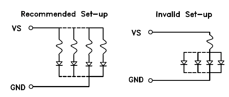
1. Protective current-limiting resistors may be necessary to operate the LEDs within the specified range.
2. LEDs mounted in parallel should each be placed in series with its own current-limiting resistor.
3. The driving circuit should be designed to protect the LED against reverse voltages and transient voltage spikes when the circuit is powered up or shut down.
4. The safe operating current should be chosen after considering the maximum ambient temperature of the operating environment.
5. Prolonged reverse bias should be avoided, as it could cause metal migration, leading to an increase in leakage current or causing a short circuit.
ESD Protection During Production
Static discharge can result when static-sensitive products come in contact with the operator or other
conductors. The following procedures may decrease the possibility of ESD damage .
1. Minimize friction between the product and surroundings to avoid static buildup.
2. All production machinery and test instruments must be electrically grounded.
3. Operator ,must wear anti-static bracelets.
4. Wear anti-static suit when entering work areas with conductive machinery.
5. Set up ESD protection areas with grounded mats for component handling.
6. All workstations that handle IC and ESD-sensitive components must maintain an electrostatic potential of 150V or less.
7. Relative humidity levels maintained between 40% and 60% in production area are recommended to avoid the build-up of static electricity – Ref JEDEC/JESD625-A and JEDEC/J-STD-033.
8.Use anti-static packaging for transport and storage.
9.All anti-static equipment and procedures should be periodically inspected and evaluated for proper functionality.
Storage conditions
1. LED Display Standard Storaged Condition Product in the original packaging material state is recommended storage conditions.
Temperature Condition: 5℃~30℃
Humidity Condition: Below 60%RH
If the storage conditions do not meet specification standards, the component pins may become oxidized requiring re-plating and re-sorting before use. Suggest customers consume LEDs as soon as possible, and avoid long-term storage of large inventories.
2.LED SMD Display Standard Storaged Condition
When the package is in factory original sealed bag.
Temperature Condition: 5℃~30℃
Humidity Condition: Below 60%RH
When the package is opened and not in factory original sealed bag.
Temperature Condition: 5℃~30℃
Humidity Condition: Below 60%RH
Storage time: Within 4 weeks (MSL as level 2a)
3.The LEDs should not be exposed to an environment where high level of moisture or corrosive gases are
present.
4.LED leadframe and soldering pads (cathode and anode) are plated with gold, tin, or other metals. Under long-term exposure to open air, the exposed pins and pads may become oxidized causing poor solderability. Therefore opened but unused parts must be stored in sealed containers. Suggest to store unused SMD Display parts in the original moisture barrier bag.
5.Moisture control for components already mounted on PCB
If the PCB will not undergo additional reflow soldering or high-temperature processes, then no special treatment is required for the mounted moisture-sensitive SMD components. If the PCB will undergo multiple reflow soldering or other high-temperature processes, including rework, then the SMD component's cumulative exposure time until the final high-temperature process must be controlled to within the specified time limit.
Terms and conditions for the usage of this document
1.The information included in this document reflects representative usage scenarios and is intended for technical reference only.
2.The part number, type, and specifications mentioned in this document are subject to future change and improvement without notice. Before production usage customer should refer to the latest datasheet for the updated specifications.
3.When using the products referenced in this document, please make sure the product is being operated within the environmental and electrical limits specified in the datasheet. If customer usage exceeds the specified limits, ArkTech will not be responsible for any subsequent issues.
4.Excess driving current and/or operating temperature higher than recommended conditions may result in severe light degradation or premature failure.
5.The information in this document applies to typical usage in consumer electronics applications. If customer's application has special reliability requirements or have life-threatening liabilities, such as automotive or medical usage, please consult with ArkTech representative for further assistance.
6.The contents and information of this document may not be reproduced or re-transmitted without permission by ArkTech.
7.When any special process such as potting is required for LED assembly, please consult with ArkTech representative before proceeding.
CATEGORIES
LATEST NEWS
CONTACT US
Name: Ms.Wendy
Mobile:0086-15861679389
Tel:0086-81725657
Whatsapp:0086 17386542651
Email:info@arktechcn.com
Add:8# HengDa CaiFu Center, JinKai Industrial Area, Wuci City, Jiang Su, China